How to Choose a 12 Port Fiber Termination Box?
Choosing a 12 Port Fiber Termination Box is not simply a matter of counting twelve adapters. The enclosure must match the cable type, connector design, installation location, and future maintenance needs. A wall-mounted box may suit a small office, while a rack-mounted model may fit a crowded data room. The difference becomes clear when technicians work inside the enclosure.
Jim Hayes, founder of the Fiber Optic Association, offers a practical principle: “A good fiber installation is one that can be tested, documented, and maintained.” That principle should guide every purchase decision. Look for a secure splice tray, clear port identification, controlled bend radius, and enough internal space for safe fiber routing. Tight trays can create sharp bends. Small errors matter.
Protection matters too. Check the box’s material, door lock, cable glands, grounding provision, and environmental rating. Indoor applications may need basic protection, while outdoor cabinets require stronger sealing against dust and moisture. Confirm whether the box supports LC, SC, or other adapters before ordering. Compatibility is easy to overlook.
A reliable 12 Port Fiber Termination Box should also leave room for inspection and repairs. Labels should remain readable after years of handling. Fiber slack should be organized, not forced behind the panel. The cheapest option may work, but it may also create costly labor later. This is where judgment becomes imperfect. Product specifications rarely reveal every installation challenge, so reviewing drawings, cable measurements, and technician feedback remains essential.
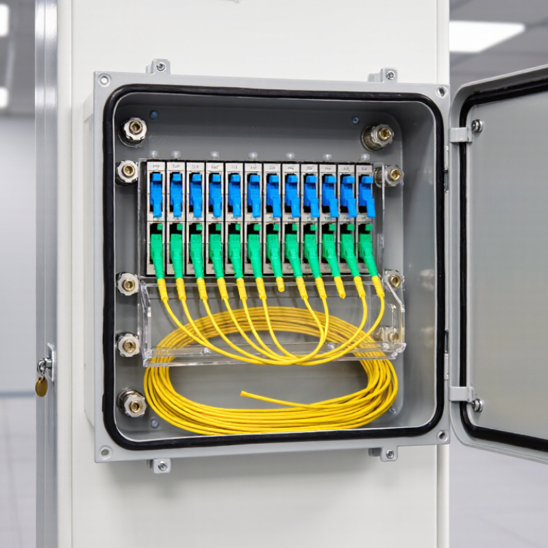
Define Capacity: Match 12 Adapter Ports to Fiber Count and Splice Load
A 12-port fiber termination box does not always serve twelve fibers. Define the adapter layout first. Twelve simplex adapters support twelve terminated fibers. Twelve duplex adapters may serve twenty-four fibers. Check the connector type, not only the product title.
The Fiber Optic Association commonly uses 0.1 dB as a planning value for a fusion splice. Allowing 0.3 dB is safer when field conditions vary. A 12-fiber cable may therefore need twelve splice positions, twelve adapter ports, and several reserved positions. For a 24-fiber cable, a 12-port box may require duplex adapters or a larger enclosure. Count active fibers, spare fibers, and repair slack separately. Do not hide spare fibers inside the working capacity.
ITU-T G.984.2 specifies GPON rates of 2.488 Gbit/s downstream and 1.244 Gbit/s upstream. Higher bandwidth does not remove physical splice limits. It can increase future fiber demand. The FTTH Council Europe’s 2024 Market Panorama also reported continued growth in fiber homes passed across European markets. That trend makes spare capacity practical, not decorative. I have seen installations fail because the box matched the adapter count but not the splice tray. A tidy enclosure can still be undersized. Recheck cable diameter, bend radius, tray capacity, and entry routing before approval. Two unused ports may be worth more than a cheaper, tightly packed design.
Verify Compatibility: LC/SC Interfaces, OS2/OM4 Fiber, and IEC 61754
Choosing a 12-port fiber termination box starts with interface compatibility, not port count. LC adapters suit dense racks because their smaller bodies conserve panel space. SC adapters offer a larger push-pull format and simpler handling in field cabinets. Do not mix them casually. I have seen installations where the connector fit physically, but the polarity and adapter layout did not match. That mistake delayed testing.
Check the fiber type carefully. OS2 single-mode fiber typically supports 1310 nm and 1550 nm links over long distances. OM4 multimode fiber is designed for short, high-speed data-center runs, commonly around 100 meters at 40/100 Gb/s, depending on the optical module. The Fiber Broadband Association’s 2024 industry report highlights continued expansion of fiber access networks, making accurate fiber identification increasingly important. Mark each port with its fiber type, route, and polarity. Keep it visible.
IEC 61754 defines connector interface dimensions and mating requirements. For LC systems, verify the applicable LC interface specification, while SC systems require the corresponding SC specification. Also inspect keying, ferrule condition, insertion loss, and return loss. A box can accept the plug and still fail the link budget. Use an optical power meter and light source after termination. Small details matter. My own preference is to leave spare labeling space, although that choice is easy to underestimate. Network layouts change more often than planned. The ITU Facts and Figures 2024 report estimated 5.5 billion people were online, increasing pressure for dependable fiber infrastructure.
Check Optical Performance: ≤0.3 dB Insertion Loss and ≥50 dB Return Loss
How to Choose a 12 Port Fiber Termination Box?
Check Optical Performance: ≤0.3 dB Insertion Loss and ≥50 dB Return Loss
A 12 port fiber termination box should protect each splice while preserving signal quality. Pay close attention to insertion loss, which measures light lost through a connection. A target of 0.3 dB or less helps maintain stable transmission, especially across multiple links. Confirm whether this value applies to each adapter, splice, or complete assembly. Specifications can be misunderstood.
Return loss of at least 50 dB is equally important. It shows how little light reflects toward the transmitter. Higher return loss usually supports cleaner signals and reduces performance problems in sensitive networks. During inspections, technicians should test at the specified wavelength, such as 1310 nm or 1550 nm. Testing conditions matter. A result without wavelength details is incomplete.
Look for sealed cable entries, secure adapters, and enough bend radius inside the enclosure. A crowded tray can create sharp fiber bends and unexpected loss. Clean connectors before testing, even when they look bright. Dust is often invisible at normal distance. I have seen excellent components fail because of poor cleaning and rushed routing. That experience makes field verification essential. Ask for factory test records, then repeat measurements after installation with a calibrated optical power meter and light source. A neat box is helpful, but measured performance is more trustworthy.
How to Choose a 12 Port Fiber Termination Box? - Check Optical Performance: ≤0.3 dB Insertion Loss and ≥50 dB Return Loss
| Configuration | Fiber Type | Adapter Interface | Max. Insertion Loss | Min. Return Loss | Splice Capacity | Cable Entry Range | Protection Rating | Recommended Use | Optical Result |
| A | Single-mode OS2 | 12 × SC/UPC | ≤ 0.30 dB | ≥ 50 dB | 24 fibers | Ø 4–12 mm | IP65 | Indoor or sheltered outdoor distribution | Pass |
| B | Single-mode OS2 | 12 × SC/APC | ≤ 0.25 dB | ≥ 60 dB | 24 fibers | Ø 4–12 mm | IP65 | FTTH, PON, and high-reflection-sensitive links | Pass |
| C | Single-mode OS2 | 12 × LC/UPC | ≤ 0.30 dB | ≥ 50 dB | 24 fibers | Ø 3–10 mm | IP54 | Compact indoor cabinets and rack distribution | Pass |
| D | Multimode OM3/OM4 | 12 × LC/UPC | ≤ 0.30 dB | ≥ 35 dB | 24 fibers | Ø 3–10 mm | IP54 | Short-distance data-center links | Return-loss target not met |
| E | Single-mode OS2 | 12 × SC/APC | ≤ 0.20 dB | ≥ 60 dB | 24 fibers | Ø 5–16 mm | IP67 | Outdoor access networks and harsh environments | Pass |
Selection note: For a 12-port fiber termination box, select a single-mode configuration with a maximum insertion loss of ≤ 0.30 dB and a minimum return loss of ≥ 50 dB. SC/APC interfaces generally provide higher return-loss performance than SC/UPC interfaces because of their angled end-face design.
Assess Protection: IP54–IP65 Enclosures and ≥30 mm Fiber Bend Radius
How to Choose a 12 Port Fiber Termination Box?
Protection should match the installation, not merely the product label. IEC 60529 defines IP54 as protection against limited dust ingress and water splashes. IP65 adds dust-tight construction and protection against water jets. For indoor cabinets, IP54 may be adequate. Outdoor walls, utility rooms, and dusty workshops deserve IP65. Check the door gasket, cable glands, drain design, and unused-entry plugs. A strong enclosure with a poor gland still fails.
Fiber routing needs equal attention. Keep at least a 30 mm bend radius unless the cable manufacturer specifies a larger limit. ITU-T G.657 fiber standards support tighter bends, but that does not excuse sharp routing inside a crowded box. The Cisco Annual Internet Report projected global IP traffic at 396 exabytes per month by 2022, showing why stable, dense connections matter. TeleGeography’s 2024 Global Bandwidth Research Service also reported continued growth in international bandwidth demand. More traffic increases the cost of a small installation mistake. Leave visible slack loops. Use radius guides. Avoid forcing a cover closed. I have seen technicians meet the bend-radius number at installation, then lose it after later maintenance. That detail is easy to miss. Check it again.
How to Choose a 12-Port Fiber Termination Box?
Compare enclosure protection levels using IEC 60529 IP-code digits, together with a design benchmark of at least 30 mm fiber bend radius for protecting fiber routing and reducing mechanical stress.
IP54 provides dust-limited protection and protection against water splashes. IP65 adds complete dust protection and protection against water jets. For a 12-port box, select the enclosure rating according to the installation environment and verify that the internal routing maintains a bend radius of ≥30 mm.